Description
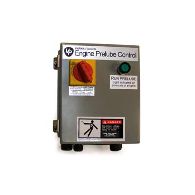
Manual Prelube Operation
- The engine prelube pump can be operated by pushing the prelube button on the control box. Additionally, the prelube pump can be operated at any of the optional remote prelube operator stations.
- The prelube pump will run while the button is pushed or the black and white wires in the control cable are connected by a switch or relay.
- The button lamp will flash while the prelube pump is running.
- When the preset prelube oil pressure is detected by the engine prelube pressure switch, the button lamp will change to solid. Note: The lamp is optional in remote prelube operator stations.
Semi or fully-automatic operation
The VARNA Products Prelube Control Unit has three external control signals that can be used to operate the prelube pump and report the state of the engine prelube pressure switch.
- The first signal is the Pressure Switch Signal. It is an input signal to the Prelube Control Unit from the engine Prelube Pressure Switch. A contact closure between two connector blocks in the Prelube Control Unit while the prelube pump is operating will illuminate the button lamp in the control unit and any connected remote lamps.
- The second signal is the Operate Pump Signal. It is an input signal to the Prelube Control Unit from a remote switch or a relay contact closure that is used to run the prelube pump. A contact closure between the two connector blocks in the Prelube Control Unit will cause the prelube pump to run. The prelube pump will continue to run until the contact closure opens.
- The third signal is button lamp signal. It is a 24-VAC output signal from the Prelube Control Unit used to illuminate any connected button lamps. This signal is derived from the Pressure Switch signal.
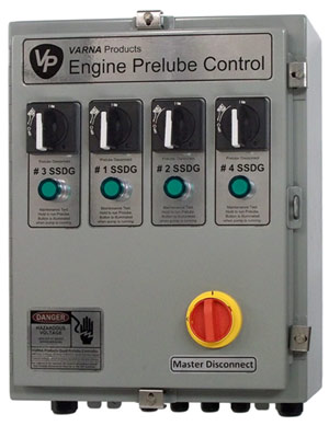
Multi Unit Controls.
These are identical to the above control with the exception that all the controls for two or more prelube systems are packaged in a single enclosure, with a single master cut off switch. We designed these for shipboard engine rooms were space can be at a premium. They may also be appealing in a multi unit standby power room or anywhere multiple engines are in close proximity.